Simulation of a composite resonance tube speaker [複合共鳴管]
2011/10/18
Outline of a composite resonance tube speaker
Its name is a composite resonance tube speaker.
Designed with a narrow middle portion of the tube is close to Mr. Tanaka model.
Although there is no mind to copy, once people will see, they will be led in the same direction.
I do not have originality!
It is because the board material, the board thickness, the elaboration and experience, and all in which there cannot be so wonderful sound differ from each other even if it copies.
This time, I plans to make and it wrote.
The makings of one plate of a single 3 × 6 feet, it is easy to make that structure has been simplified.
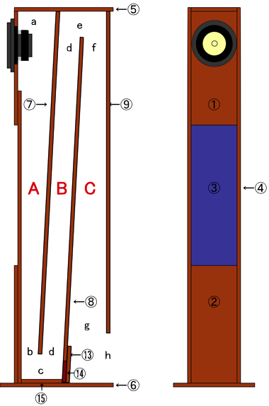
Fig.1
Specifications
Composite resonance tube speaker specifications
Rendering type resonator was a tall boy speaker in Fig.1.
Board Material : Lauan (thickness 12mm)
Size : 15.4cm wide (lower plate: 23.4cm)
Depth : 28cm (lower panel: 32cm)
Height : 100cm
Inside dimension :13.0cm width
a = 10cm , b = 5cm, c = 6.5cm, d = 6cm,
e = 6.5cm, f = 7cm, g = 10cm, h = 13cm
Goals bass : 50Hz
Speaker Unit Available
: FE103-En-S • Fe108Eσ • FE88ES-R etc.
Folded time : Twice
Others.
Tall-Boy speaker has no grasp location, and split baffle ① ② ③ for handling parts.
Part of the plate subjected to plea ⑦, and the intake of the sound-absorbing material.
Simulation
The free software "The design program for its original work speakers " using the performed simulations of the resonance tube with a tapered resonance tube and back loaded horn .
The speaker unit is FE108Esigma.
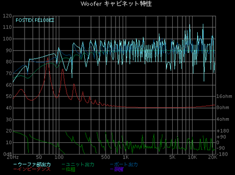
1. Assuming back loaded horn
The A section of Fig.1 was assumed to be back loaded horn's air chamber (8.2-litre).
So (b), is a cross-sectional area of 65 square centimeters, about 50 percent more than the 42 square centimeters of a Super Swan.
Loading does not start in air chamber which is too large by the simulation of a back loaded horn.
It seems that the low part fell slowly, the peak & bottom has appeared in around 100Hz, and phase inversion happens.
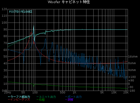
Va = 8.2-litre, l = 1.83m, r1 = 4.5cm, r2 = 6.4cm
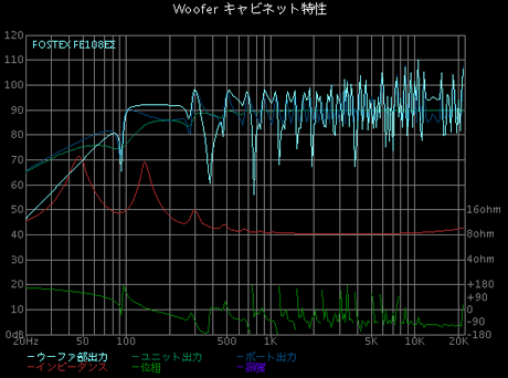
2. B&C tubes were assumed to be a resonance tube with taper.
It calculated it as A (air chamber) like 1., having assumed A or later to be a resonance tube (1.83 m) with a taper-less. After maintaining a level to 50 Hz, it has fallen rapidly.
Moreover, near 150to220Hz has fallen.
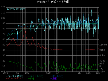
l = 1.83m, r1 = 5cm, r2 = 6.4cm
3. Whole tube assumed that it was a resonance tube without a taper.
So, if the resonant length A + B + C, will be calculated λ / 4 is about 33Hz.
The result of a "Original work speaker design program" is extended to 33 Hz.
However, around 140 Hz falls intensely from the average level of sound pressure.
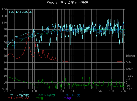
l = 2.68m, r1 = 5cm
4. The whole tube assumes that it is a resonance tube with a taper.
This has been extended to fall slowly from about 35Hz in 90Hz. The decline seen between 100Hz from 160Hz.
It compares without a taper with a taper and the growth of bass level is slightly bad.
It seems that the part bass level goes up.
l = 2.68m, r1 = 5cm, r2 = 6.4
5. When the tube of A-B-C resonates independently
If tube sets to 85 cm, λ /4 will be 100 Hz.
Simulation when the 85cm single tube operates as a resonance tube.
Loading has started 100Hz to 300Hz.
0.85m, r1 = 5cm
6. The result of a simulation
This speaker operates with a resonance tube.
By the capacity of a 8.2-liter air chamber, it is too large and can not operate a back loaded horn.
On the other hand, there is no stress of a corn and it can expect fine sound.
If it does not experiment in the quantity of low frequencies, it is unknown.
This is the point.
On the other hand, the growth of low frequencies is expected.
Although a simulation also shows, it will be forced trial and error by the strong sound of the peculiarity peculiar to a resonance tube which comes out of a mouth.
The idea is to adjust the angle of the tube C in the concept stage is a quantitative measure of low frequency, because it is being squeezed in the tube B, there is not clear how much effect.
It would also fall from 100Hz to 200Hz in the vicinity of the simulation results.
Either way, phase inversion may occur immediately after the sound pressure is loaded, there is a strong decline.
Emitted from the mouth as the interaction of this frequency harmonics.
And I do not make sense to calculate this?
So Let's make a suitably
Drawing board
Parts list
Unit (cm)
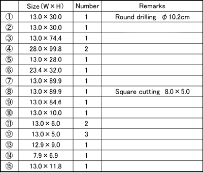
*Board a small fine was omitted.
Drawing board(3×6)for 1Speaker
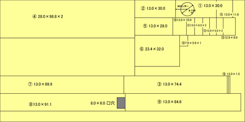
*There also do not need to draw on the board of adjustment.
Reference Blog
丹波漆器.com Speaker essay「Essay41」
http://www.nexyzbb.ne.jp/~tanbashikki/essay41.html
The design program for its original work speakers
http://www.asahi-net.or.jp/~ab6s-med/NORTH/SP/index.htm


コメント 0